- Brand Name: Aprilbeacon
- Origin: Mainland China
- Model Number: RFID tool
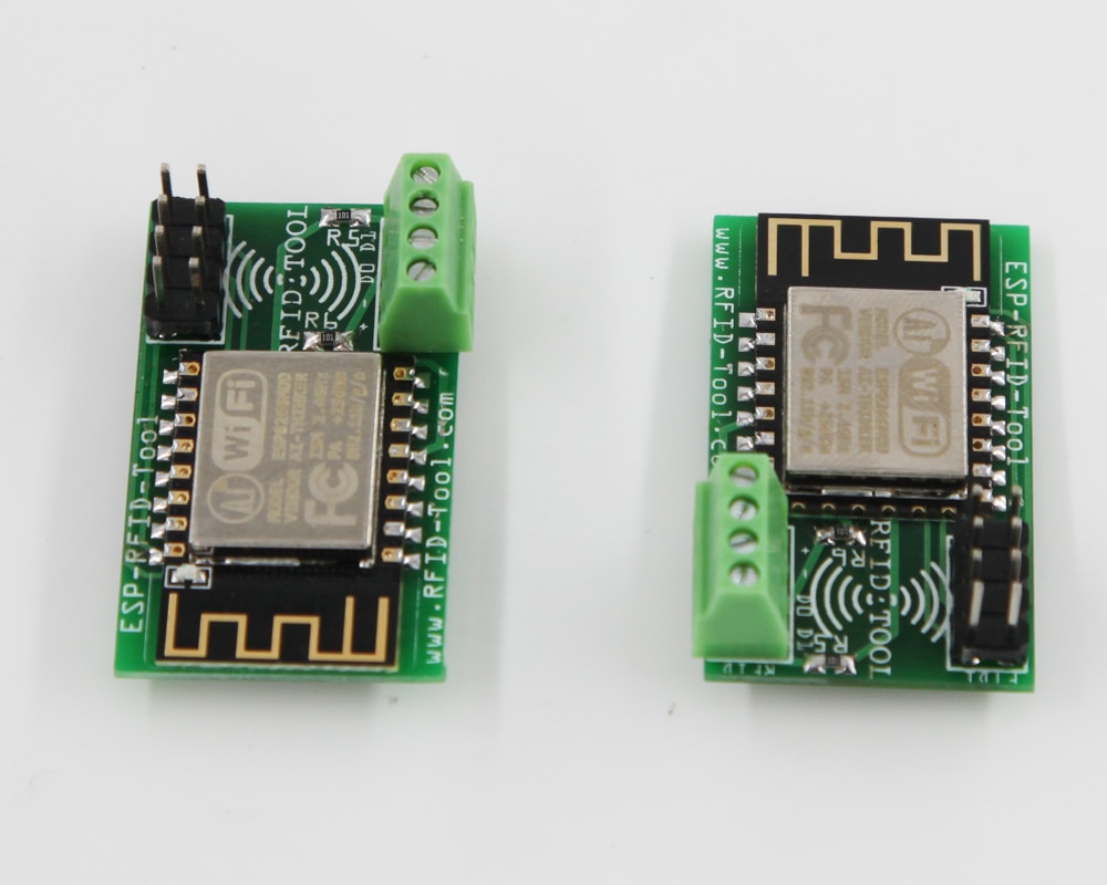
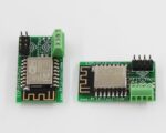
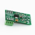
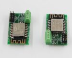
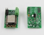
A tool for logging Wiegand data and also for testing devices contain a Wiegand Interface.
NOTE Wiegand RFID reader is not included.
We just update the new one with punch down connector, please chek the link if you are interested:

https://www.aliexpress.com/item/1005004337781814.html?
Intended use cases
-
Security researchers performing red team assessments.
-
Capturing card values to later be cloned.
-
Replaying raw binary captures.*(see note below)
-
Fuzzing access control systems.*(see note below)
-
To create a standalone device for testing badges and or card readers without the need for a Wiegand Controller.
-
Add a battery and a card reader to make the unit portable.
-
Add a benchtop power supply to use for testing hardware.
-
Installers troubleshooting issues with a card reader or the data lines out in the field or back in the office.
-
Hobbyist experimenting with various systems that utilize a Wiegand Interface.
-
Simulating an access control system using multiple units of ESP-RFID-Tool.
What is it?
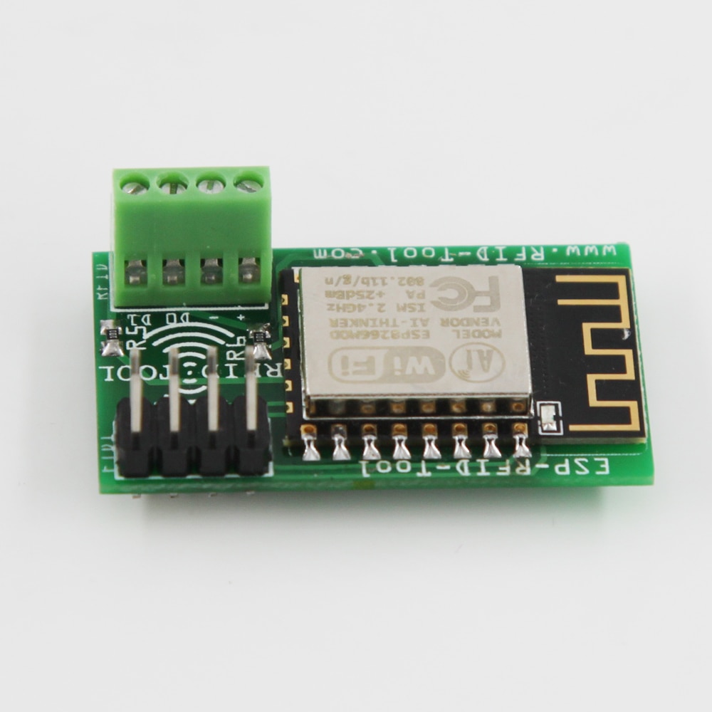
A universal data logger that captures the raw binary data from a standard 5V Wiegand Interface. The device is capable of logging the credentials for access control systems or nearly any device that utilizes a Wiegand Interface such as RFID card readers, pin pads, magnetic stripe systems, and even some biometric readers. Wiegand Interfaces also do not have to be limited to just access control systems. The main target group for this device is 26-37bit HID cards. For known card types both the binary and hexidecimal data is displayed directly in the log file for easy badge identification and also in case a clone of a card may be needed. For unknown card types only the raw binary data is shown.
How do you install it?
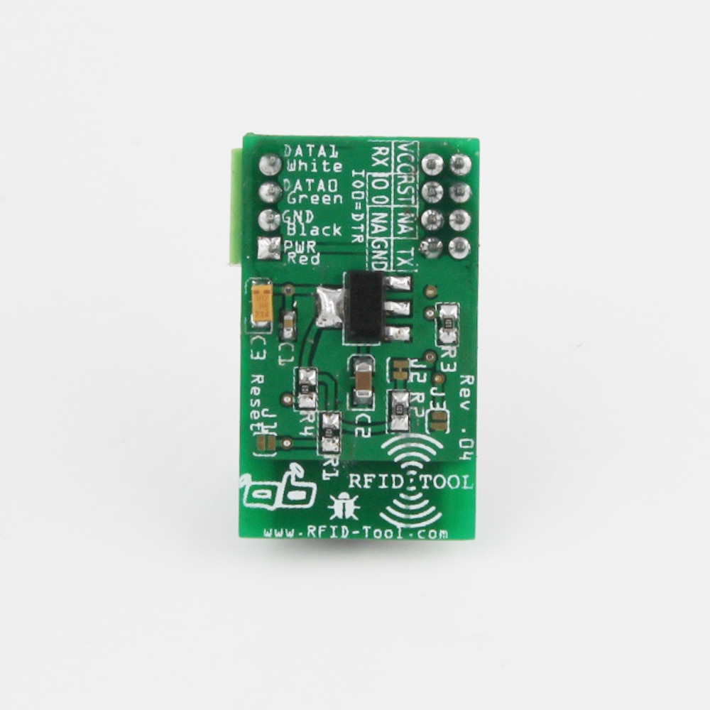
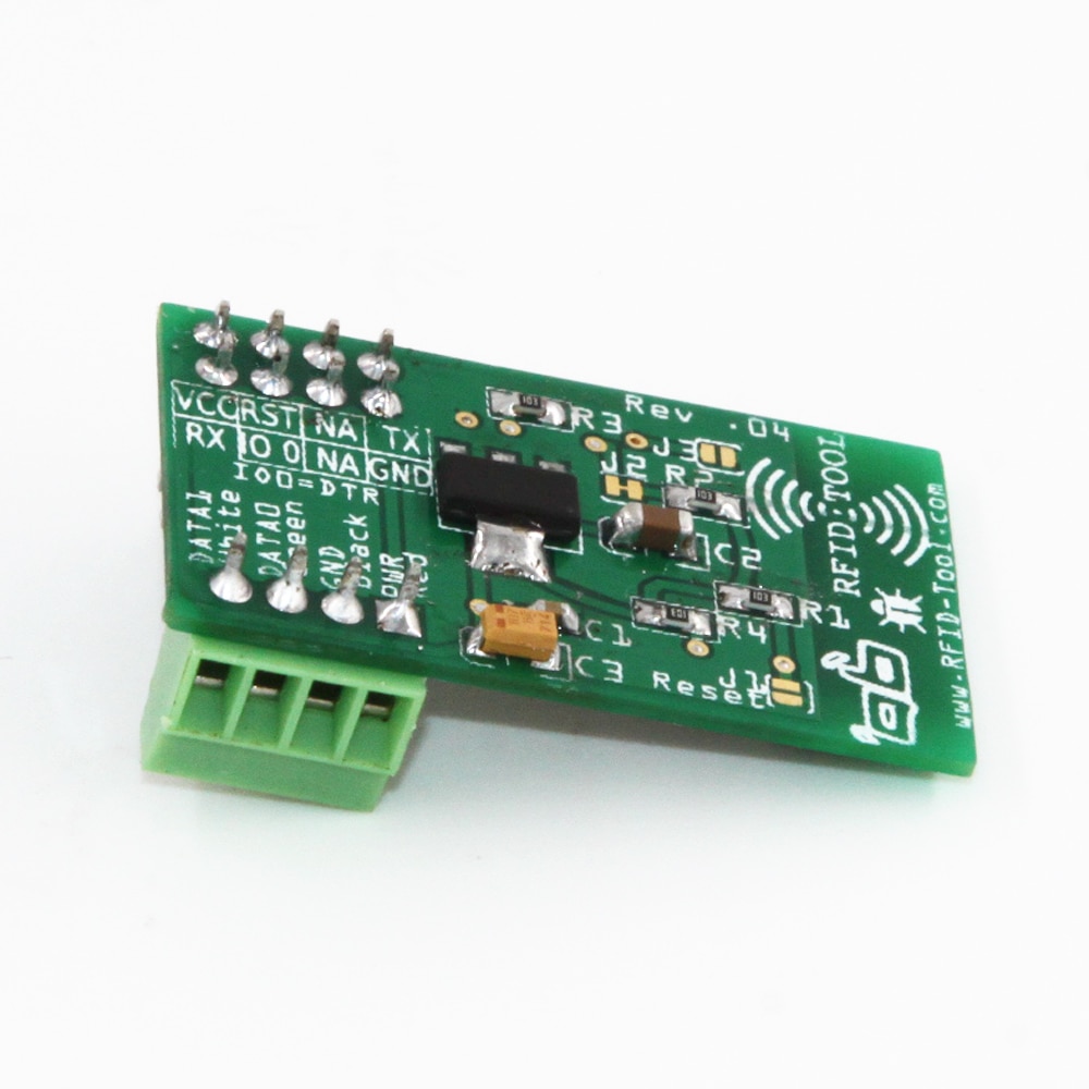
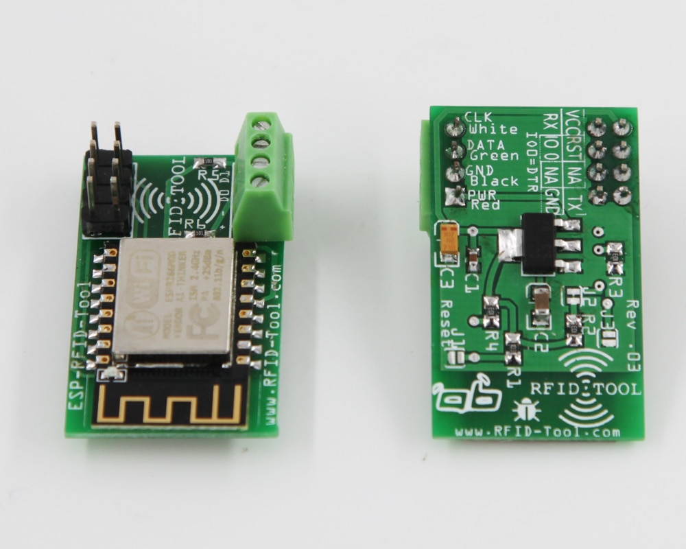
The device may be installed directly into an existing system drawing its power from the preexisting wiring or it can also be used to turn a reader into a standalone portable unit for data logging when a battery is added. Wiring is simple and consists of 4 wires, (+), (-), D0(Green), and D1(White). The device is capable of operating on voltages ranging from around 4.5V up to a maximum of 12V. Commonly found voltages are 12V and 5V.
How do you access the logs?
Access to the log files and various settings is provided via a web based interface. The device has WiFi capabilities and can be set up to spawn its own access point or set to connect to an existing network. In the event you get locked out of the web interface you can bridge the J3 jumper on power up or while resetting the device to regain access without losing your log files.
I want to know a little more…
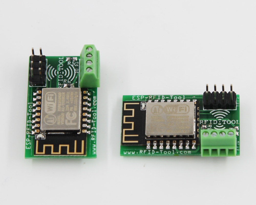
The hardware is based on an ESP12F WiFi chip with a full TCP/IP stack and Microcontroller Unit. The software is open source licensed under the MIT License and will be released the day the product is launched. The software will reside in this GitHub repo so it may be reviewed by the community. We will accept various pull requests from the community after being reviewed if it improves the value of the device for others. The software was written in the Arduino IDE so both hobbyist and professionals will have no issue modifying the code if they so choose. A Wiegand Interface operates using 3 wires, a ground, Data0, and Data1. A zero is sent when D0 goes low and a one is sent when D1 goes low, the other line remains high during this time. The timing is 40uS from low to high on a line with 2mS between bits. The software logs this binary output to a file and if the device thinks it is a known card format the preamble is guessed(not sent by card reader but it is the same for all cards of a specific format, our primary target is 26-37bit HID cards) and both the raw binary and hexidecimal data is logged. For unkown card formats only the raw binary output is logged with no guess at the preamble and without showing the data in hexidecimal format to prevent confusion. If you know what kind of card was captured, simply look up the preamble and add it to the beginning of the binary then typically convert it to hexidecimal format to make a clone of a card. It is possible the card is actually an unknown format and the preamble was guessed incorrectly with the device thinking it was a known card format(the guess is based on the bit count output by the reader), if this is the case in the log file there is a literal space in the binary between the preamble and the card data, simply ignore the preamble. When replaying a captured credential(see note below) you do not include the preamble as that is not output by the card reader but instead you only replay(see note below) the actual card data as output from the reader. You only need to worry about the preamble if making a clone of a card. The primary function of this device is for logging the raw binary data as output from a Wiegand Interface. You can read from 1 bit all the way up to 4,096 bits. The default buffer setting only allows 52 bits and must be manually increased from the settings page accessible from the web interface.
*Experimental TX Mode
The device was made with minimal hardware to keep costs extremely low and in reach of hobbyist and also so security professionals can buy multiple units and also use them without the fear of losing a unit. This being said there are no level shifters on the board.(It is possible that in the future a PRO version may be released) This means that with the current hardware the device can work with a 3V3 Wiegand Interface as well as a 5V Wiegand interface because the hardware operates at 3V3 and is also 5V tolerant. The drawback of this is that not all 5V Wiegand controllers are guaranteed to be triggered when replaying or fuzzing data because only 3V3 is output from the device. There is also a risk when the device is in TX mode and the output goes low for 40uS, if the device were to also receive data during this time there will be a short. For this reason be sure that absoulutely no cards are being scanned while the device is in TX mode. The device does not go into TX mode until you press on a form submit button and as soon as the data is done being transmitted it goes back into listening mode. For the reasons above TX mode is for experimental use only and was designed primarily for easily debugging the software when making changes.(two units were tied together)
Use transmit mode at your own risk, it is not officially supported. Consider it a bonus in the software.
History
I pushed the design for the original prototype to GitHub back in September 11, 2016. I was using an Adafruit Feather Huzzah running some code that I had modified. At the time no sort of Wiegand logger existed offering WiFi capabilities and providing an easy to use web interface for accessing the log files.(I could not find one so I created it) During the second evolution of the project I decided to design dedicated hardware and I lightly upgraded the software. It was open source hardware and it was out there on GitHub but still not easily available to the masses. Not everyone is confident in surface mount soldering and even for me it was time consuming assembling boards for personal use. It was then that I realized there is a need for an affordable device like mine to be mass produced so anyone that needs one can have access to it. During the third stage I redesigned both the software and the hardware and decided to contact April Brother to see about manufacturing it and selling it for a fair price. That is when ESP-RFID-Tool was born.
Installation Notes
-
Make sure the reader outputs data in the Wiegand format
-
Connect D0 on device to D0 on reader
-
Connect D1 on device to D1 on reader
-
Connect + on device to + on reader
-
Connect – on device to – on reader
-
OPTIONAL: Connect 4.5-15V battery into the same + and -(only if building a portable unit, do not add a battery if implanting device into an existing installation, or if you do use a battery do not connect the + wire from the existing installation to your device, only tie in the GND -)
-
NOTE: At a minimum D0, D1, and GND(-) must be connected to the reader for proper function, no matter the power source.
Updates
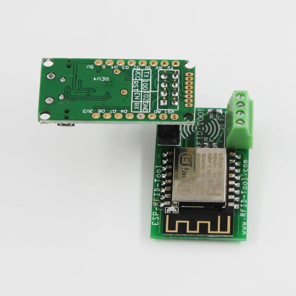
Software updates will be available from the Github page. You may update the software directly from the web interface or by using ESP Flasher R4 by April Brother, there is a compatible pinout on the board for flashing.
How To Wire ESP Flasher And ESP RFID TOOL
From Web Interface:
-
Download one of the latest releases from "gitub-rfidtool"
-
Login to the device’s admin panel and upgrade the firmware.
You can get video on YouTube: "ESP RFID Tool"




Reviews
Clear filtersThere are no reviews yet.